What Are Parker Rotary Actuators?

Time:2026-09-10 Author:Charlotte
0%

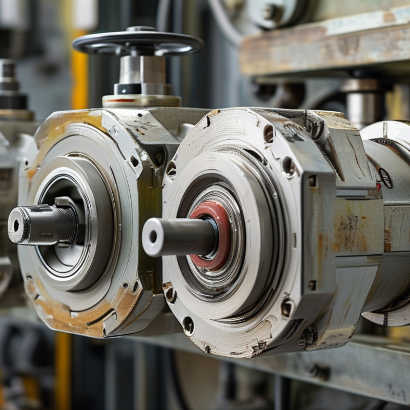
Parker Rotary Actuators convert fluid power into controlled rotary motion. They support precise turning, indexing, clamping, and valve operation. Their compact bodies fit crowded hydraulic and pneumatic systems. Their torque also remains dependable under demanding industrial loads.

The global industrial automation market was valued at approximately USD 200 billion in 2023, according to Grand View Research. Its report expects continued growth through 2030, driven by smarter factories and connected equipment. MarketsandMarkets also identifies motion control as a major automation requirement. Parker Hannifin reported nearly USD 20 billion in fiscal 2024 sales, showing the scale behind its motion-control portfolio.

Performance depends on more than torque ratings. Engineers must examine pressure, rotation angle, cycle speed, mounting space, seal life, and control accuracy. A poorly selected actuator can waste energy and create unstable movement. Small errors matter.

Tom Williams, Parker Hannifin’s former chairman and chief executive, described the company’s practical mission as “Engineering your success.” That principle fits Parker Rotary Actuators, but it should not replace testing. No single market report isolates every rotary actuator application. Published figures can also combine hydraulic, pneumatic, and electric technologies. This limitation deserves attention.

This guide explains how Parker Rotary Actuators work, where they fit, and how engineers evaluate them. It connects catalog specifications with real operating conditions. The goal is useful understanding, not easy promotion. Performance must be measured.
What Are Parker Rotary Actuators?

Definition and Basic Function of Parker Rotary Actuators

A rotary actuator is a mechanical device that converts fluid power into controlled rotary motion. Instead of moving a rod in a straight line, it turns a shaft through a set angle. Common ranges include 90, 180, or 360 degrees. The shaft can open a valve, position a gripper, or rotate a fixture. This movement is usually powered by compressed air or hydraulic pressure.

Inside, pressure acts on a piston, vane, or helical mechanism. The internal design transfers that force into torque around the output shaft. Torque describes the turning force available at the shaft. Directional control valves manage forward and reverse rotation. Adjustable stops can limit the angle and improve positioning accuracy. Some models also include sensors for feedback.

Sizing requires more than matching the shaft diameter. Engineers must examine load weight, friction, cycle speed, pressure, and stopping shock. A heavy fixture may need extra torque during startup. Mounting alignment matters too. Small errors can create side loads and early wear. The basic definition sounds simple, but real installations are less predictable. Temperature changes, air leaks, and uneven loads can alter performance. I have found that theoretical torque values can feel generous in actual machinery. Testing under working conditions remains important.

Main Components and Operating Principles

What Are Parker Rotary Actuators?

Main Components and Operating Principles

A rotary actuator converts compressed air or hydraulic pressure into controlled angular movement. Its main components include a housing, drive shaft, bearings, seals, fluid ports, and internal torque-producing parts. Depending on the design, these parts may include a vane, rack-and-pinion set, or helical piston mechanism. The output shaft connects to a valve, gripper, indexing table, or other machine element. Seals prevent pressure loss, while bearings support the shaft during repeated rotation.

The operating principle is straightforward. Pressurized fluid enters one chamber and pushes against an internal surface. This force creates torque around the shaft, producing clockwise or counterclockwise rotation. A control valve changes the pressure path and reverses movement. Mechanical stops or adjustable cushions limit the rotation angle and reduce impact at the end of each stroke. In hydraulic models, higher pressure can produce greater torque, but temperature and fluid cleanliness also affect performance.

Torque depends on pressure, effective area, and the actuator’s mechanical design. A small seal leak may cause slow movement, even when system pressure appears normal. Misalignment can create side loads and shorten bearing life. No design is perfect. Actual performance may differ from catalog values because friction, load inertia, and installation errors interact. During maintenance, technicians should check shaft play, port leakage, mounting bolts, and unusual noise. These simple observations often reveal problems before positioning accuracy declines.

Types of Parker Rotary Actuators

What Are Parker Rotary Actuators?

Types of Rotary Actuators

Rotary actuators convert fluid or electrical energy into controlled angular movement. They rotate valves, tooling, grippers, and indexing tables. The main types include pneumatic, hydraulic, and electric rotary actuators.

Pneumatic actuators use compressed air for quick, clean motion. They suit packaging lines and light industrial equipment. Vane models are compact and provide smooth rotation. Rack-and-pinion models deliver stronger torque and adjustable angular movement. Hydraulic actuators handle higher loads and harsh working conditions. They are useful where force matters more than speed. Electric actuators offer precise positioning, programmable motion, and quieter operation. However, they may require more control hardware and careful installation. Helical designs can produce high torque within a small space. Their efficiency depends on correct sizing and lubrication.

Tips: Match torque, rotation angle, speed, and duty cycle before choosing an actuator. Check the load’s inertia, not only its weight. A heavy load may still start gently, while a light load can shock the mechanism. Verify mounting space, shaft alignment, and environmental exposure. Dust, moisture, and temperature can shorten service life. In field testing, incorrect cushioning often causes vibration near the endpoint. That detail is easy to overlook. Selection is not always obvious. When specifications conflict, prioritize safe stopping, repeatable motion, and maintainable components.

Performance Characteristics and Selection Factors

What Are Parker Rotary Actuators?

Performance Characteristics and Selection Factors

Rotary actuators convert fluid power into controlled angular motion. Their performance depends on torque, rotation angle, speed, and operating pressure. A compact unit may deliver strong torque, yet move too quickly for accurate positioning. In practice, engineers should compare rated torque with the real load, including friction and startup resistance. Load inertia also matters. A heavy arm can overshoot, even when the actuator appears correctly sized.

Selection begins with the application, not the catalog number. Define the required angle, cycle time, duty cycle, and mounting space. Check whether the actuator must stop at fixed positions or follow adjustable motion. Shaft loading deserves attention because radial or side loads can shorten bearing life. Environmental details are equally important. Dust, moisture, temperature changes, and washdown conditions may affect seals and materials. Pneumatic systems usually offer fast movement, while hydraulic systems often provide higher force and smoother control. Neither option is automatically better. That assumption needs review.

Tips: Add a safety margin, but avoid excessive oversizing. It can reduce responsiveness and increase energy use. Test the actuator with the actual linkage when possible. Linkage geometry changes the effective torque through the stroke. Review cushioning settings too. Poor cushioning may create vibration, noise, and premature wear. Keep a record of pressure, cycle time, and temperature during trials. Small measurements often reveal problems that specifications miss.

Industrial Applications and Maintenance Considerations

Rotary actuators convert fluid pressure or electrical energy into controlled rotary motion. In industrial equipment, they turn valves, position clamps, index workpieces, and move robotic joints. Their compact design suits machines with limited installation space. Some models deliver partial rotation, while others provide continuous movement. Selection depends on torque, rotation angle, speed, load, and operating environment. A small mismatch can create expensive downtime.

Maintenance begins with the installation area. Keep the actuator free from metal dust, water spray, and excessive heat. Inspect mounting bolts for movement or uneven loading. Check couplings for misalignment, because small angular errors increase bearing stress. During operation, listen for clicking, grinding, or irregular movement. These signs often appear before complete failure. Record cycle counts, pressure readings, temperature, and inspection dates. Useful records improve troubleshooting.

Lubrication requires care. Too little lubricant increases friction, but excess lubricant can attract abrasive particles. Follow the equipment manufacturer’s specified lubricant and service interval. Inspect seals for cracking, leakage, or hardening. Replace damaged seals before contamination reaches internal components. Pneumatic systems also need clean, dry air and properly adjusted flow controls. Hydraulic systems require contamination checks and stable fluid levels. Electrical versions need secure wiring and protected connectors. Maintenance plans are rarely perfect. A missed inspection can happen, especially during production pressure. That weakness should be documented and corrected, not hidden. Technicians should also review unusual loads after tooling changes, because yesterday’s settings may not suit today’s process.

FAQS

: What is a rotary actuator?

: It converts fluid or electrical energy into controlled shaft rotation. The shaft may turn 90, 180, or 360 degrees. It can open a valve or position a fixture.

How does a rotary actuator create torque?

Pressure or electrical force acts on an internal piston, vane, or helical mechanism. This force turns the output shaft. Torque is the shaft’s available turning force.

What types of rotary actuators are available?

Pneumatic models use compressed air for quick motion. Hydraulic models handle heavier loads and harsh conditions. Electric models provide precise, programmable positioning.

How should I choose the correct actuator size?

Check torque, rotation angle, speed, pressure, duty cycle, and load inertia. Do not match size by shaft diameter alone. A heavy fixture may need extra startup torque.

Where are rotary actuators commonly used?

They operate valves, clamps, grippers, indexing tables, and robotic joints. Their compact shape helps inside crowded machinery. Some designs offer partial rotation, while others rotate continuously.

What installation problems can reduce actuator life?

Poor shaft alignment creates side loads and bearing stress. Loose mounting bolts can cause uneven movement. Dust, moisture, heat, and water spray may shorten service life.

What maintenance does a rotary actuator need?

Inspect seals, couplings, mounting bolts, wiring, and connectors regularly. Use the specified lubricant and service interval. Too much lubricant can attract abrasive particles.

What signs may indicate a developing fault?

Listen for clicking, grinding, vibration, or irregular movement. Check for pressure changes, leaks, temperature increases, and poor endpoint stopping. Small symptoms often appear before failure.

How can operating records improve troubleshooting?

Record cycle counts, pressure, temperature, inspection dates, and unusual loads. These details reveal changing conditions. Records may be incomplete, but hiding gaps makes diagnosis harder.

Why should an actuator be tested under real conditions?

Theoretical torque can seem generous. Air leaks, temperature changes, friction, and uneven loads alter performance. Testing the actual machine remains necessary. Perfect sizing is not guaranteed.

Conclusion

Parker Rotary Actuators are mechanical devices designed to convert fluid power into controlled rotary motion. They are commonly used to rotate, position, or hold machine components through a specific angle. Their main parts typically include a housing, vane or piston mechanism, drive shaft, seals, bearings, and ports for fluid supply and exhaust. During operation, pressurized air or hydraulic fluid acts on an internal surface, producing torque that moves the shaft smoothly and reliably.

Different designs may provide single-rack, double-rack, vane, or limited-angle movement, depending on the required torque, rotation range, speed, and precision. When selecting Parker Rotary Actuators, users should consider load size, operating pressure, cycle frequency, environmental conditions, mounting space, and control requirements. These actuators are suitable for material handling, packaging, clamping, assembly, and automated processing equipment. Regular maintenance, including leak inspection, seal replacement, lubrication where appropriate, alignment checks, and contamination control, helps maintain performance, extend service life, and support safe, efficient operation.

Charlotte

Charlotte

Charlotte is a seasoned marketing professional with a deep understanding of the company's portfolio and a passion for elevating its presence in the market. With a keen eye for detail and a commitment to excellence, she ensures that our professional blog is regularly updated with insightful articles......