A 12v Rotary Actuator can look simple on a bench: a compact housing, two power leads, and a rotating output shaft. Choosing one for real equipment is less straightforward. Load torque, travel angle, operating time, duty cycle, backlash, and environmental protection all shape performance. A unit that moves freely without a load may stall when a linkage binds or a door seal adds resistance. Small details matter.
Industry reports offer useful context, but not a universal answer. The U.S. Department of Energy’s Industrial Electric Motor Systems Market Opportunities Assessment examines motor-driven equipment and efficiency, while market analyses from firms such as MarketsandMarkets track broader electric-actuator demand. These sources cover wider categories; they do not establish one best specification for every 12-volt application. For selection, compare manufacturer datasheets and test the actuator under the actual load, supply voltage, and mounting conditions. Measure current, too. It can reveal strain before failure becomes obvious.
One source limitation matters: no reference articles were supplied, so I cannot verify a named 12V rotary-actuator expert’s exact quotation. Inventing one would weaken trust. This guide instead focuses on checkable specifications and practical trade-offs. The right choice is rarely the one with the largest torque figure alone. Fit, control, and repeatability count. Sometimes, the datasheet still leaves questions.
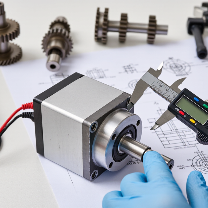
Start with the movement. Define whether the shaft needs continuous rotation, a limited angle, or repeated indexing. Measure the required angle, travel time, and stopping accuracy. A 90-degree valve turn differs greatly from a slow 270-degree flap adjustment. Record the load at the shaft, not only the weight of the attached part. Friction, linkage geometry, and startup resistance can multiply the torque demand. If the actuator must hold position without power, identify that requirement early. A gearbox, brake, or mechanical lock may be necessary.
Then describe the operating conditions. Check the available 12V supply under load, including voltage drop through cables and connectors. Starting current can exceed running current by a wide margin. Choose a controller and fuse that tolerate this peak safely. Note the duty cycle: ten brief movements per hour are not the same as continuous cycling. Ambient temperature, dust, moisture, vibration, and installation angle also affect reliability. For outdoor equipment, specify the enclosure protection level and cable sealing method. These details are easy to overlook.
Use measured data whenever possible. A quick hand calculation is useful, but it should not replace a loaded test. In practice, my first torque estimate is often too optimistic. Leave a sensible margin, yet avoid oversizing without reason. Excess capacity can increase cost, current draw, and mechanical stress. Define feedback needs as well: limit switches may suit simple end positions, while variable positioning may require an encoder or potentiometer. Document normal and abnormal conditions, including jammed motion and repeated stops. This specification gives the 12V rotary actuator a realistic job to perform.
| Selection Dimension | Typical Requirement | Practical Data Range | Why It Matters | Recommended Specification |
|---|---|---|---|---|
| Power Supply | Vehicle, battery, or control-system power | 12 VDC nominal; approximately 10.5–14.4 VDC in many mobile systems | Voltage variation affects speed, current draw, and available torque | Select an actuator rated for 12 VDC and verify its operating voltage range and polarity protection |
| Required Rotation Angle | Partial positioning rather than continuous rotation | Common output angles: 90°, 180°, 270°, or adjustable travel | The actuator must reach the target position without mechanical overtravel | Choose a fixed-angle or programmable-limit model with sufficient travel adjustment |
| Motion Profile | Open/close, index, tilt, divert, or regulate flow | Discrete positioning or repeated reciprocating movement | Different loads require different control methods, travel times, and feedback options | Define the number of positions, direction changes, acceleration needs, and stopping method |
| Output Torque | Torque needed to overcome load, friction, and starting resistance | Light mechanisms: below 5 N·m; medium mechanisms: 5–20 N·m; heavy mechanisms: above 20 N·m | Insufficient torque can cause stalling, overheating, or incomplete travel | Calculate static and breakaway torque, then add a safety margin of about 25–50% |
| Load Type | Balanced, unbalanced, frictional, or inertia-dominated load | Load torque may change significantly with position | Gravity and inertia can produce peak torque that is much higher than running torque | Include worst-case starting torque, end-stop impact, and off-center load effects |
| Operating Speed | Fast response or controlled movement | Typical partial-turn speeds: approximately 5–60 seconds per 90° | Higher speed can reduce positioning time but may increase impact, noise, and current demand | Specify the required travel time under the actual load, not at no-load conditions |
| Duty Cycle | Occasional adjustment or frequent cycling | Low duty: fewer than 10 cycles/hour; moderate duty: 10–60 cycles/hour; high duty: over 60 cycles/hour | Motor heating and gear wear depend on cycle frequency and running time | Check rated duty cycle, maximum on-time, rest time, and thermal limits |
| Position Feedback | Basic end-position control or closed-loop positioning | Limit switches, potentiometer, Hall sensors, encoder, or digital feedback | Feedback improves repeatability, fault detection, and intermediate positioning | Use limit switches for end positions and proportional or encoder feedback for variable positioning |
| Control Interface | Manual switch, relay, PLC, or electronic controller | Two-wire polarity reversal, three-wire control, analog input, or digital command | The control method determines wiring, switching capacity, and integration complexity | Match the actuator signal type with the controller and provide appropriate overcurrent protection |
| Current Consumption | Battery-powered or continuously connected system | Running current often ranges from below 1 A to several amperes; stall current is higher | The power supply and switching devices must handle startup and stall current | Size the fuse, wiring, relay, and power supply using measured or specified peak current |
| Environmental Protection | Indoor, outdoor, dusty, wet, or washdown environment | Ingress protection commonly ranges from basic enclosed designs to IP65/IP67-class construction | Water, dust, salt, and chemicals can damage gears, seals, sensors, and electrical connections | Choose an enclosure rating suitable for the actual exposure and protect connectors from corrosion |
| Temperature Range | Stable indoor temperature or outdoor temperature changes | A common industrial design target is approximately −20°C to +60°C, subject to the actual product rating | Temperature affects lubricant viscosity, battery voltage, seals, and motor performance | Verify both operating and storage temperature ratings for the complete actuator assembly |
| Mechanical Installation | Limited space, shaft coupling, or bracket-mounted assembly | Key factors include shaft size, mounting pattern, allowable side load, and available clearance | Misalignment and excessive radial or axial load can shorten gear and bearing life | Confirm mounting dimensions, shaft geometry, alignment tolerance, and load direction before selection |
| Backdriving and Holding | Load must remain fixed after power is removed | Gear reduction may resist backdrive, but holding capability varies by design | An unpowered load may move because of gravity, vibration, or external force | Use a self-locking mechanism, brake, or external mechanical lock when fail-safe holding is required |
| Safety and Reliability | Potential pinch points, jammed loads, or critical positioning | Protection may include current limiting, thermal protection, limit switches, and emergency stop control | A jam or wiring fault can cause overheating, mechanical damage, or unsafe movement | Add overload protection, end stops, fault feedback, and a safe-state strategy appropriate to the application |
A geared DC actuator suits basic forward and reverse movement. A servo offers feedback-based positioning, while a stepper provides repeatable movement. A stepper may lose position under excessive load.
Confirm whether the range is continuous, fixed, or programmable. Measure the angle with the mechanism installed; a stated 180° range may not be exact. Leave a small clearance near the stopping point.
Check rated voltage, running current, and startup surge. A 60-watt actuator draws about 5 amps at 12V before losses. Test with the actual supply. A weak adapter can cause stalling or repeated resets.
Check shaft diameter, bolt spacing, bracket stiffness, and available clearance. Slight bracket flex can change the final position. I once focused too much on torque and overlooked alignment.
Identify whether control uses polarity reversal, PWM, relays, or a dedicated controller. Check its current rating against running and stall current. Verify feedback signals and limit-switch wiring before installation.
Limit switches can stop movement at set positions. Current limiting and thermal protection may reduce damage during jams or repeated cycles. Guard moving parts. Disconnect power before inspection.
Match the ingress protection rating to actual dust and water exposure. Inspect connector seals, cable entry, corrosion resistance, and operating temperature limits. “Water-resistant” alone is vague.
Run it at 12V under the real load, then observe movement, heat, startup current, and stopping accuracy. Check emergency stopping and cable fit, too. A datasheet can still mislead.
Choosing the right 12v Rotary Actuator begins with defining the required motion and application conditions. Determine whether the system needs continuous rotation, limited-angle movement, precise positioning, or controlled reversing. Then evaluate the expected rotation range, load direction, operating frequency, and available space. Torque and speed should be calculated based on the load, friction, acceleration, and safety margin, while the duty cycle must match how often and how long the actuator will operate.
Electrical and mechanical compatibility are equally important. Confirm that the actuator’s 12V power requirements suit the available supply, including startup current, and check that its mounting dimensions, shaft design, and control method fit the equipment. Finally, compare protection against dust, moisture, vibration, and temperature changes, along with safety features such as overload protection, limit control, braking, and emergency stopping. A careful review of these factors helps ensure reliable performance, efficient operation, and a longer service life.

 Weitai Hydraulic